Input Shaping Calibration Pattern
Based on the excellent work of @tombrazier
Caution! Only for Cartesian printers. CoreXY kinematics are not yet tested.
Use this form to generate G-code that you can use to calibrate your Input Shaping Damping Frequency and Zeta/Damping factor. Default values apply to standard PLA filament and a 0.4mm nozzle.
The generated G-code files print Frequency Sweeps (zigzag patterns with increasing speeds) to find Resonant Frequencies (frequencies to dampen) and Zeta/Damping Factors for the X axis (left-to-right) and Y axis (front-to-back).
Three separate G-code files are generated for download:
- Damping Frequency to find Resonant Frequency for X and Y (displayed in the box below)
- X Zeta/Damping Factor (not shown)
- Y Zeta/Damping Factor (not shown)
Fill out the form and press Generate G-code to create the test patterns. Use the Download * as file buttons to save the results.
Settings | G-code | ||||
Printer Info | |||||
| Diameter (mm) of the filament used for the tests | |||||
| Nozzle Temperature (°C) | |||||
| Bed Temperature (°C) | |||||
| Retraction distance after pattern (mm) | |||||
| Line width (mm) | |||||
| Layer Height (mm). If pattern is not clear, try to increase Layer Height | |||||
| Fan Speed (%) | |||||
Speed | |||||
| Printing speed when not in pattern (mm/s) | |||||
| Travel Speed (mm/s) | |||||
| Retract Speed of the extruder (mm/s) | |||||
| Printing and transition acceleration/deceleration (mm/s^2) | |||||
| Jerk for X and Y when not in pattern. -1 to use pattern default | |||||
| Junction Deviation when not in pattern. -1.0 to use pattern default | |||||
Print Bed | |||||
| Size (mm) of the bed in X | |||||
| Size (mm) of the bed in Y | |||||
Pattern | |||||
| Maximum frequency (Hz) for X pattern | |||||
| Maximum frequency (Hz) for Y pattern | |||||
| Offset the Z (mm) for manual layer adjustment | |||||
| Level the bed or load a saved mesh (UBL only!) before printing. Bed leveling must be activated in Configuration.h! | |||||
| Usually 1.0 | |||||
| Align the Z gantry by running the G34 command | |||||
Notes:
- Max X Frequency and Max Y Frequency should be high enough to reach Resonant Frequency. The moving bed of a "bedslinger" printer usually has a lower Resonant Frequency corresponding to its greater mass. Adjust values after your first test print and as-needed to match the printer.
- Use Bed Leveling requires a probe.
- Printer and other parts (e.g., filament spool) may resonate and emit sounds during Frequency Sweeps.
- The printer's stepper motors may skip steps leading to lost position —aka "layer shift"— at or above the Resonant Frequency. This is normal behaviour.
- Be aware that high speeds may exceed what your extruder can handle. A 60Hz frequency corresponds to 120mm/s (7200 mm/min) movement speed. For the default 0.5mm line width and 0.2mm layer height the machine needs to extrude 12 cubic mm of filament per second. Know your extruder's limits.
- If the test patterns show asymmetry or vibration in the Z direction, linear motion might have slack or flex (e.g., from loose roller wheels). See the image below.
- Input Shaping can affect Linear Advance. If Linear Advance is enabled, calibrate K-factor after calibrating Input Shaping.
Examples
The following images demonstrate some test patterns.
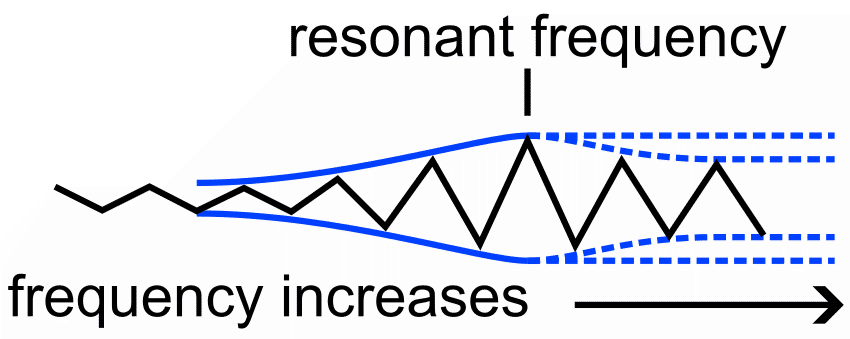
Damping Frequency Pattern theory
- Frequency sweep patterns are printed for both axes.
- As the Frequency approaches the Resonant Frequency the vibration Amplitude increases.
- At Resonant Frequency amplitude reaches it's peak.
- Beyond Resonant Frequency amplitude may remain high or decrease.
- Measuring the distance (mm) from the beginning of the pattern to the point of amplitude peak reveals Resonant Frequency, where frequency is this distance divided by 2.
- To reduce ringing, Input Shaping tries to dampen Resonant Frequency, aka. Damping Frequency.
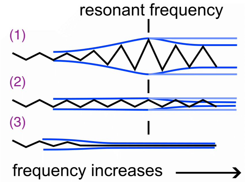
Zeta/Damping Factor theory
- Damping Factor sweep patterns are printed for both axes.
- The Damping Factor controls damping. (See the image below.)
- Damping Too Low: Vibration is not cancelled at Damping Frequency.
- Damping Correct (critical): Vibration is cancelled at Damping Frequency.
- Damping Too High: Vibration is reduced too aggressively also below Damping Frequency.
- To find the best value look for the zigzag pattern with the most uniform amplitude at and below the Damping Frequency and the same or decreased amplitude above the Damping Frequency.
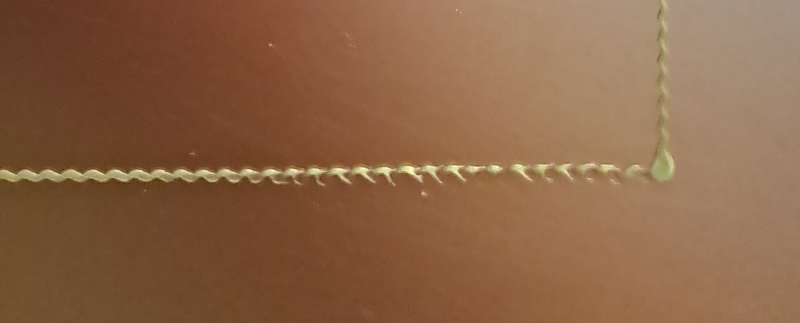
Damping Frequency Pattern - Example 1
Zeta/Damping Factor Pattern - Example 1
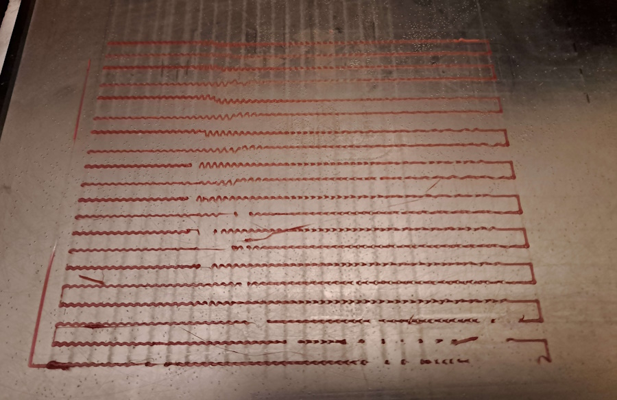
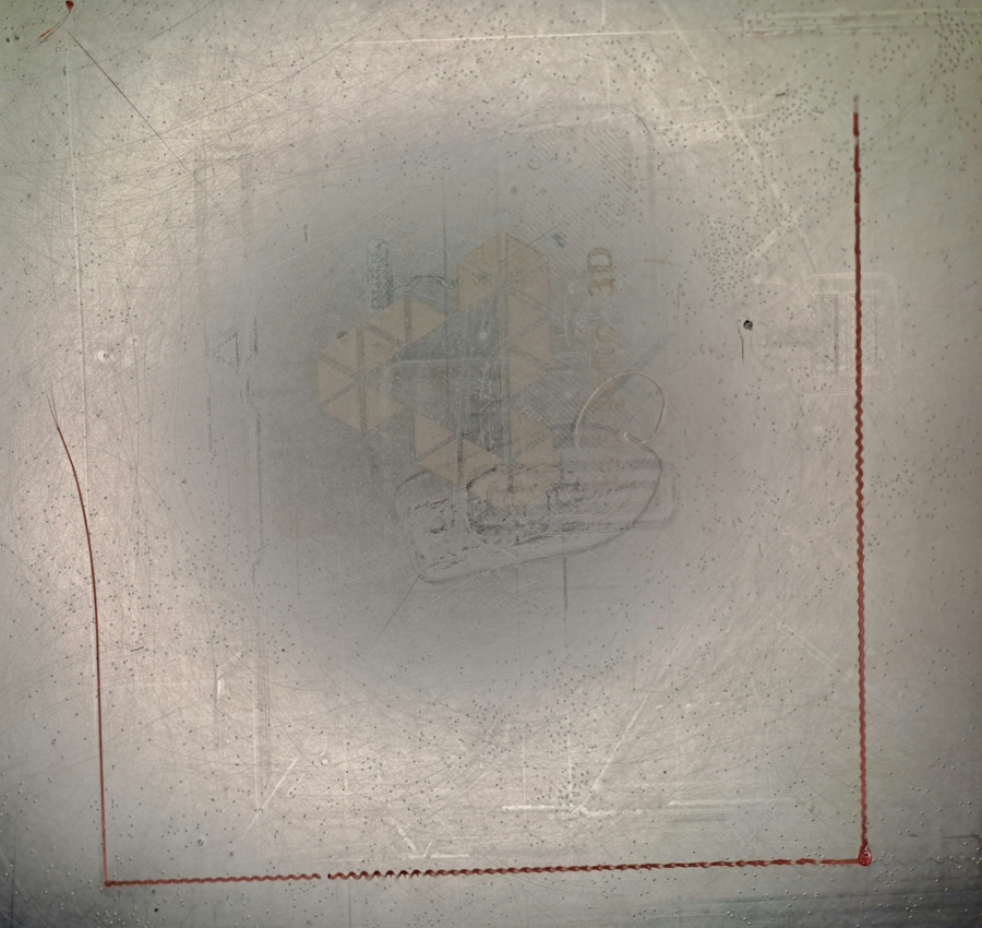
Damping Frequency Pattern - Example 2
This print consists of:
- Frame (back and left lines)
- Y Frequency Sweep (horizontal at front)
- Slowdown
- X Frequency Sweep (vertical on left)
- Slowdown
The Resonant Frequency for Y is around 39Hz (78mm). The Resonant Frequency for X is not so clear, 55-60Hz (110-120mm).
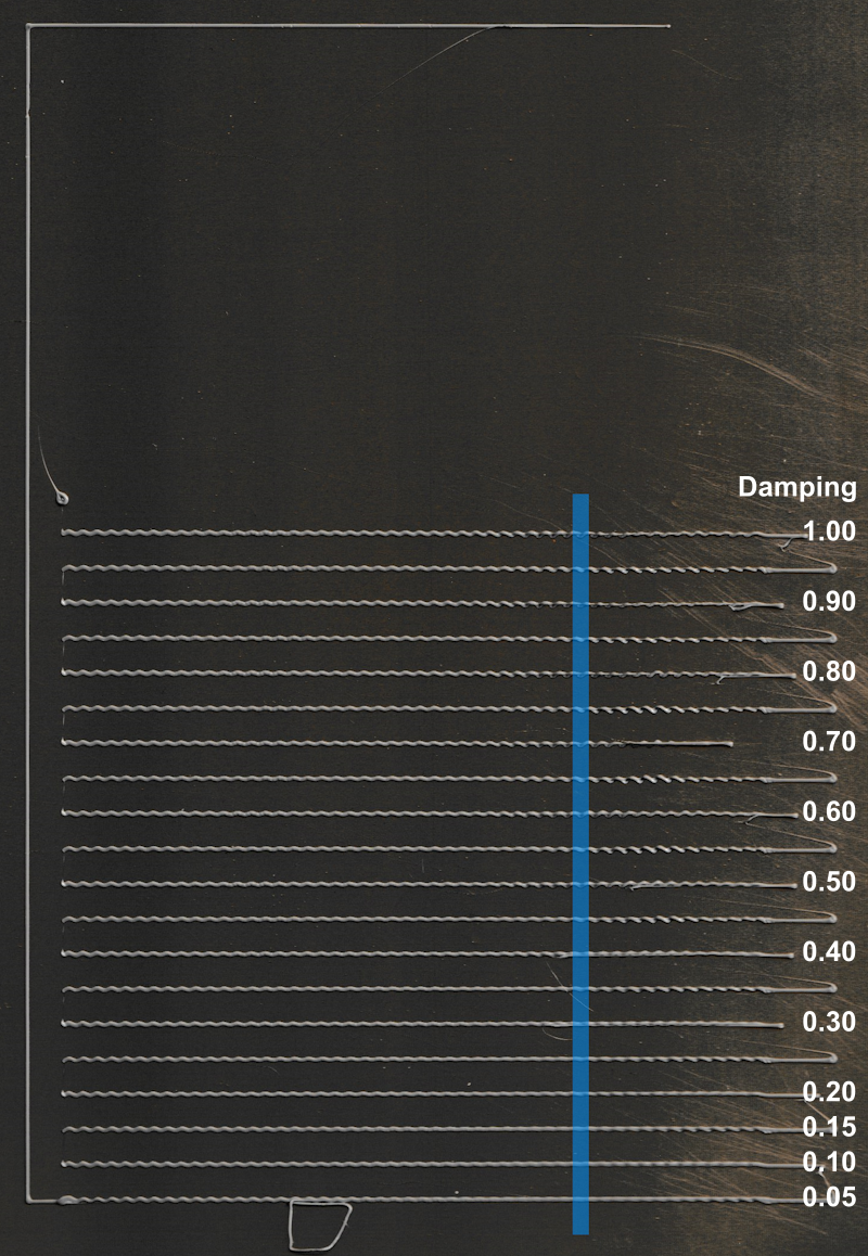
Zeta/Damping Factor Pattern - Example 2
This print consists of:
- Frame (back and left lines)
- Y Frequency Sweeps at increasing Damping Factor values
Damping Factor values start from 0.05 and increase by 0.05.
0.40 (8th pattern) looks the best.
Note! Zeta/Damping pattern for X is vertical. (The leftmost line is part of the anchor and is not relevant to Damping Factor values.)
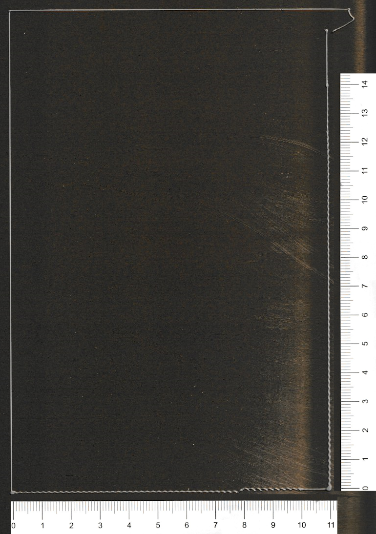
Example of loose roller wheels
During this pattern the bed may have been moving and/or rotating in directions other than just Y.
The roller wheels of the bed were too loose and tightening them improved the pattern.